Measurements
The RAMI4ATM phase is focused on reflectance measurements in the presence of the atmosphere. This is the first RAMI exercise involving the atmospheric component, and the experiment focuses on observations made at both the top-of-atmosphere (TOA) and bottom-of-atmosphere (BOA) levels.
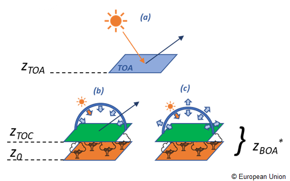
The $z_{BOA}$ (*, as shown in Figure 1) is defined to be equal to either the Top of Canopy level $z_{TOC}$ or $z_0$, depending on the inclusion or not of an explicit vegetation component. For instance, for HOM25_LAM, HOM35_LAM, HOM45_LAM $z_{BOA}$ is equal to $z_{TOC}$. For all the remaining surfaces $z_{BOA}$ is $z_0$.
RAMI4ATM assumes that the virtual sensor has a field-of-view covering the entire horizontal dimension of the scene.
RAMI4ATM foresees five different measurements subdivided into
At Top of Atmosphere, RAMI4ATM experiment requires to simulate the bidirectional reflectance factor in the principal (brfpp) and orthogonal (brfop) planes. Being the incoming radiation field at TOA purely direct, no change of the measurement definition with respect to the previous RAMI phases is required.
The spectral Bi-directional Reflectance Factor (BRF) is defined as the radiant flux density (or radiance) $L^\uparrow$ exiting from a target area in a given viewing direction ($\theta_r$, $\phi_r$) and a given direct illumination direction ($\theta_i$, $\phi_i$) normalized by the equivalent quantity leaving from an infinitely large Lambertian and ideal background $L^\uparrow_{lamb}$ (e.g. 100% reflectance ).
For instance, being $L^\uparrow_{lamb}=\frac{1}{\pi}E_{\odot}^\downarrow\cos(\theta_i)$ at TOA the BRF defined in Equation 1-a corresponds to TOA reflectance expressed as:
where $E_{\odot}^\downarrow$ is the extraterrestrials spectral irradiance.
This should be modelled for $\theta_r$ ranging between 1° and 75° in steps of 2° in the principal and orthogonal planes, and reformatted as indicated in RAMI-V (two blocks for each measure to account for $d\phi = \phi_i-\phi_r$ equal to 0° (back-reflection) and 180° (forward) for brfpp, and d$\phi=\pm$90° in brfop.
| <meas> Identifier tag | Tag meaning |
|---|---|
| brfop | Bi-directional Reflectance Factor in the orthogonal Plane |
| brfpp | Bi-directional Reflectance Factor in the principal plane |
At the bottom of atmosphere the incoming irradiance is formed by a direct and an anysotropic diffuse component determined by the atmospheric properties, the sun zenith angle and the radiative coupling between surface and atmosphere.
The participants should compute the Hemispherical-Directional Reflectance Factor (hdrf), in the principal and orthogonal planes.
A general definition of the reflectance factor is given in the theoretical framework section [Equation 7].
For the particular case of HDRF the integrals over the exiting infinitesimal solid angles $d\omega_r$ in the direction ($\theta_r,\phi_r$), cancels out and the equation looks like
where $L^\downarrow$ is representative of the combined direct and diffuse incident radiant flux densities, and $f_r$ is the bi-directional reflectance distribution function [Schaepman-Strub et al., 2006] Equation [10]. [Jupp, 1997] (Section 4.1) represents the same quantity as
For the Bi-Hemispherical Reflectance (bhr) we advise to refer to the analogous definition given in [Schaepman-Strub et al., 2006] Eq [22] or [Jupp, 1997], Section 4.2.
Equations [2-a] and [3-a] should be solved for actual illumination conditions.
Equations [2-b] and [3-b], were adopted from [Jupp, 1997] and were listed here for their attractive simplicity and intuitiveness.
In analogy with the brf at TOA, the hdrf should be modelled for $\theta_r$ ranging between 1° and 75° in steps of 2° in the principal and orthogonal planes, and reformatted as indicated in RAMI-V (two blocks for each measure to account for $d\phi = \phi_i-\phi_r$ equal to 0° (back-reflection) and 180° (forward) for hdrfpp, and d$\phi=\pm$90° in hdrfop.
All measurements, including the bhr, can be simulated for any of the illumination geometry proposed ($\phi_i = 0$° and $\theta_i$ = 0°, 30°, 60°, 75°).
| <meas> Identifier tag | Tag meaning |
|---|---|
| bhr | Bi-Hemispherical Reflectance |
| hdrfpp | Hemispherical Directional Reflectance Factor in the principal plane |
| hdrfop | Hemispherical Directional Reflectance Factor in the orthogonal plane |
The general equation for the representation of the reflectance in any arbitrary illumination-viewing geometry can be written by the ratio between the reflected $d\Phi(\theta_r,\phi_r)$ and the incident $d\Phi_i(\theta_i,\phi_i)$ radiant flux (units $W$) relevant to a reference surface of area $dA$ ($m^2$) and flowing through the solid angles $\omega_i$ ($sr^{-1}$) and $\omega_r$ [Nicodemus et al., 1977].
The elemental fluxes of [Equation 4] are defined as the irradiance ($dE$) across the elemental area ($d\Phi = dE\cdot dA$). Equation 4 that can be further expanded to define fluxes in terms of radiance $L(\theta,\phi) = \frac{d^2\Phi} {d\Omega dA}$, where the projected solid angle is $d\Omega = cos\theta d\omega$, and $d\omega = sin\theta d\theta d\phi$ is the infinitesimal solid angle.
In the notation of [Equation 4] the symbols $\omega_i$ and $\omega_r$ are used to represent the different possible illumination and reflectance integrating limits defining the nine types of reflectance shown in Table 3. They are generally indicated as
All the combinations pertaining to directional are theoretical quantities that cannot be measured in real conditions. They are abstraction that may be valid for very small solid angles, and where the fluxes can be considered constant.
| i $\backslash$ r | Directional ($d\omega_r$) | Conical ($\omega_r$) | Hemispherical ($2\pi$) |
|---|---|---|---|
| D ($d\omega_i$) | bi-directional [a] | directional-conical | directional-hemispherical |
| C ($\omega_i$) | conical-directional | conical-conical | conical-hemispherical |
| H ($2\pi$) | hemispherical-directional [b] | hemispherical-conical | bi-hemispherical |
The bidirectional reflectance distribution function $f_r$ (units $sr^{-1}$) is defined such that the exiting (from $dA$) radiance in the direction $(\theta_r,\phi_r)$ can be expressed in terms of the incident radiant flux density $dE_i = L_i \cdot d\Omega_i$ as
and it describes the intrinsic reflectance properties of the surface. It can be used to define the reflectance in all the other configurations of [Table 3].
Expliciting the integrals over the solid angles in [Equation 1] of the flux densities and using [Equation 2] to model the upwelling component, we obtain
where $dA$ disappeared being it common to (i) and (r) quantities, and $\omega$ symbols can assume all the different values defined in [Table 1] (i.e. d$\omega$, $\omega$ or $2\pi$). This is the general equation we will develop further below to describe the three reflectance configurations required to be simulated in RAMI4ATM.
In practical remote sensing the concept of Reflectance Factor ($R$, dimensionless [$0;\infty[$) is used. It is defined by the ratio between the exiting radiant flux $d\Phi_r$ and the exiting radiant flux $d\Phi_r^{id}$ from an ideal (lossless) perfectly diffuse reflector (with $f_r^{id} = 1/\pi$) in the same illumination conditions
For isotropic incident flux only (or the configurations in which $L^\downarrow$ can be considered constant within the limits of integration), $R=\pi f_r$. Ground measurements of reflectance are performed by either measuring the downwelling and upwelling flux or using a perfect diffuser standard panel to define the irradiance reference.
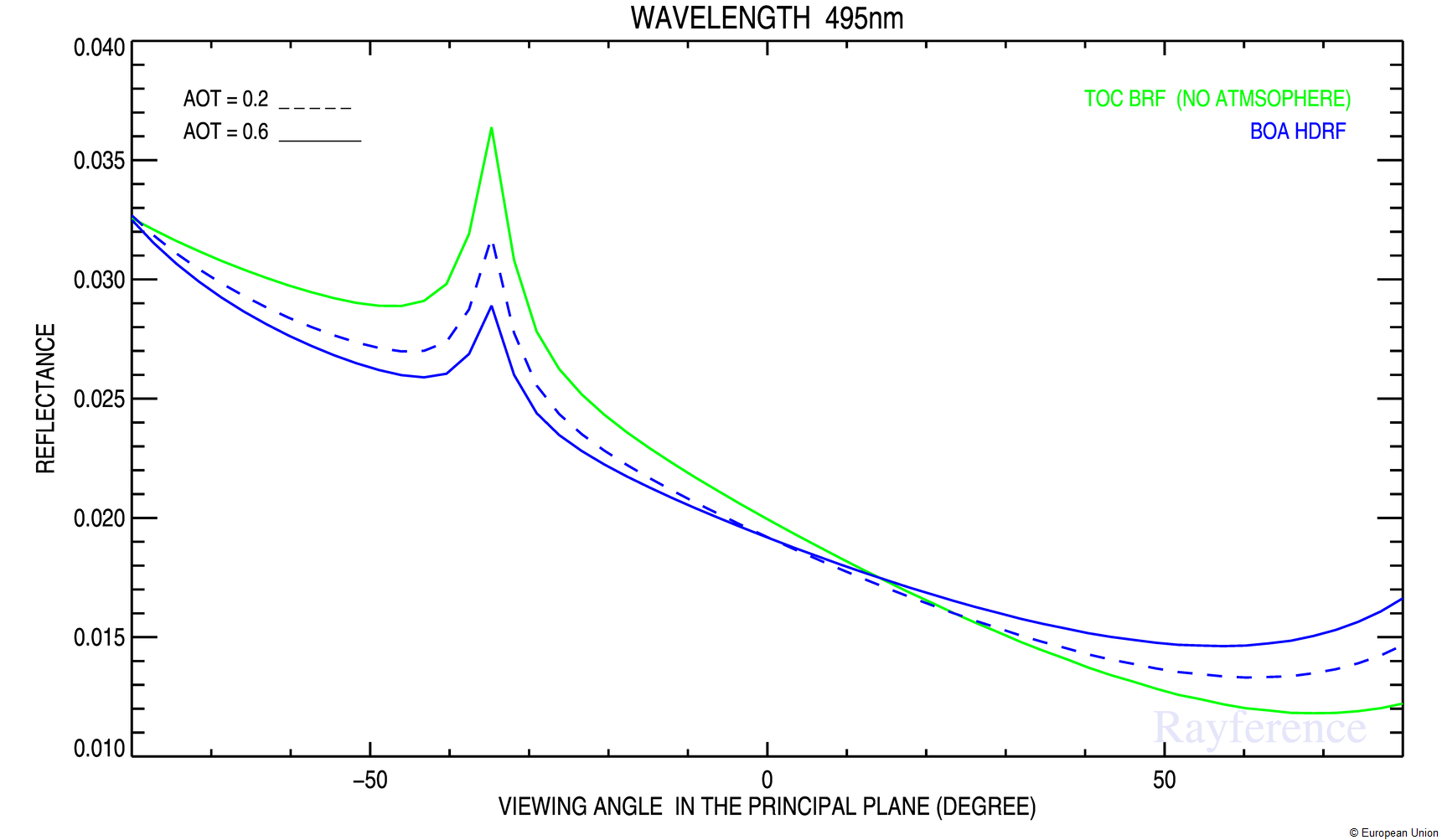
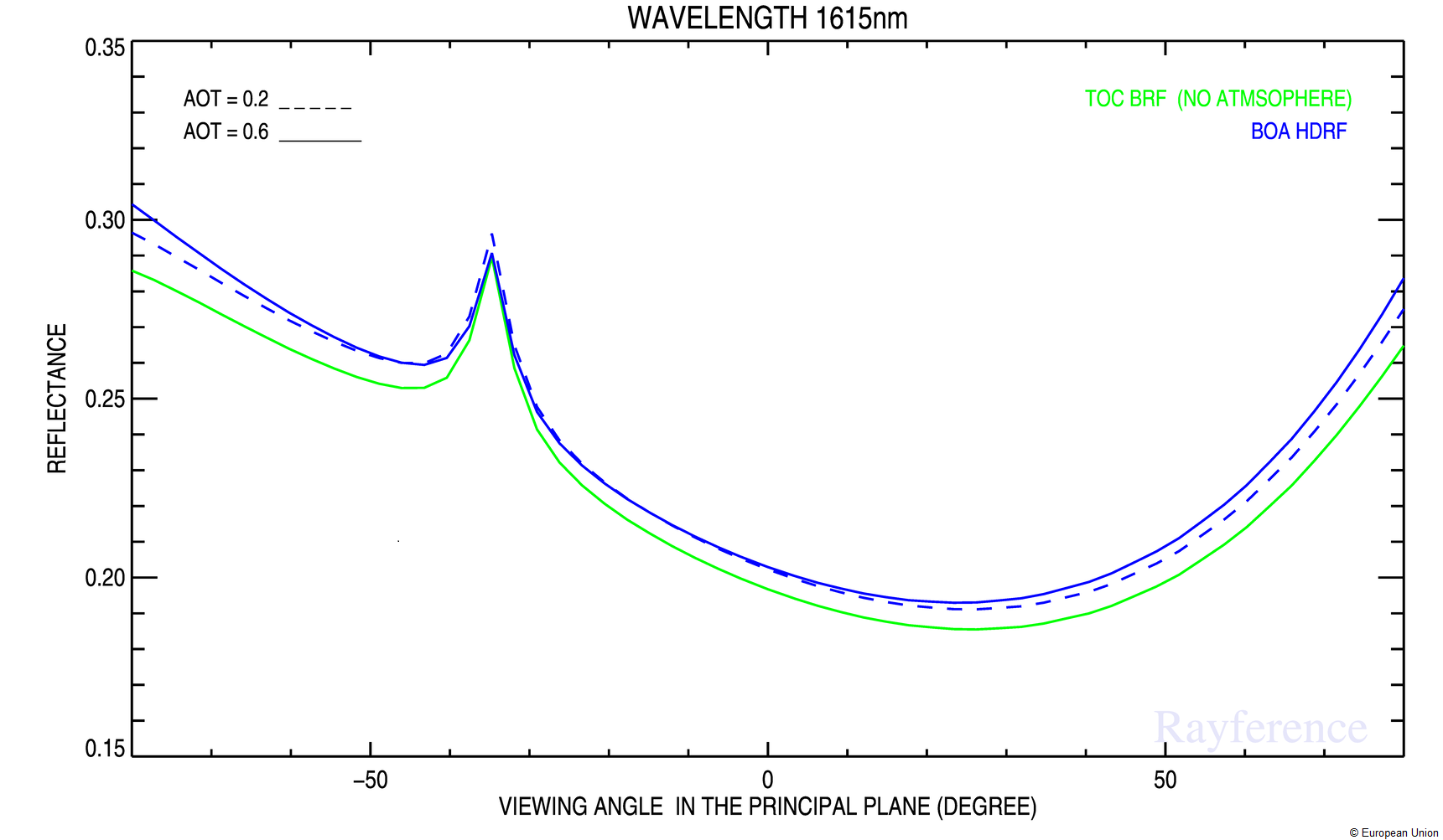
Figure 2 shows various examples of the bidirectional reflectance factor and the hemispherical directional reflectance factor in two different wavelengths in the visible and near infrared.