Abstract heterogeneous canopies with a constant slope
RAMI IV phase
This set of experiments is suggested to simulate the radiative transfer regime in the red and near infra-red spectral bands for heterogeneous leaf canopies situated on an incline of constant slope. For energy conservation purposes the abstract tree crowns are inclined and the background is kept horizontal rather than having a background that is sloping and trees that are upright.
The canopy is thus represented by a large number of identical, non-overlapping and inclinded cylindrical objects that are located over and only partially covering a horizontal plane standing for the underlying background.
Each individual cylinder contains a 'cloud' of oriented finite-sized disc-shaped scatterers representing the foliage. These Bi-Lambertian foliage elements are characterized by specified radiative properties (reflectance, transmittance) defined separately for both the visible and near-infrared spectral domains. The orientation of the normals of the foliage elements (scatterers) follows a uniform (or what is sometimes called a spherical) distribution function, i.e., the probability to be intercepted by a leaf is independent of the direction of travel of the radiation (see the definitions page). The background surface follows a Lambertian scattering laws.
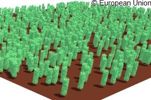
The figure exhibits graphical representations of the 4 constant slope heterogeneous canopy scenarios for HET23 & HET24 (15° inclination).
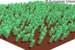
The figure exhibits graphical representations of the 4 constant slope heterogeneous canopy scenarios for HET33 & HET34 (30° inclination).
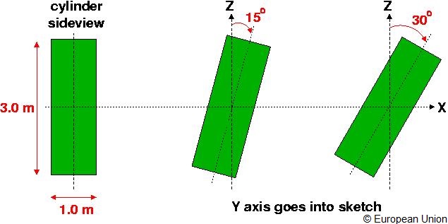
As can be seen in the image below, the cylindrical objects (when placed upright) have a height of 3.0 m, a radius of 1.0 m, and a leaf area index of 4.05 m² ⁄ m². Two different inclinations of the cylinders are envisaged: 15 degree and 30 degree, respectively. These inclinations can be obtained by rotating the cylinder (centered at the origin 0,0,0 ) along the Y axis such that the positive Z axis moves towards the positive X axis. In the canopy the cylindrical objects have their center coordinates located between heigths of 2.0099 m and 2.0101 m.
Overall two different canopy densities, two different slopes (i.e., cylinder inclinations) and four different illumination conditions will be presented. To address the needs of different RT models, both a statistical scene description, as well as ASCII files with the exact coordinates of the scatterers and the cylinder locations in the scene are provided.
The figure exhibits cylindrical objects (when placed upright).
Sparse heterogeneous canopy with a constant slope of 15 degree
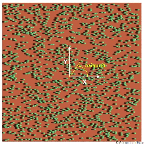
The table below provides the details required to build and run a RT model on the sparse heterogeneous cylinder canopy with a constant inclination of 15 degree. Also indicated are the X and Y axes with the azimuth angle counting scheme.
experiment
HET23
( X × Y × Z) [m × m × m]
101.30 × 101.0 × 3.58
(Xmin, Ymin, Zmin) [m, m, m]
−50.65, −50.5, 0.0
(Xmax, Ymax, Zmax) [m, m, m]
+50.65, +50.5, 3.58
Scatterer shape
Disc of negligible thickness
Scatterer radius [m]
0.0075
Foliage scattering law
Bi-Lambertian
LAI of individual (upright) cylinder
4.05
radius of cylinder [m]
0.5
height of (upright) cylinder [m]
3.0
cylinder center height range [m]
2.0099 - 2.0101
Scatterer normal distribution
Uniform
Number of cylinders
1274
LAI of scene
0.396058
Background scattering law
Lambertian
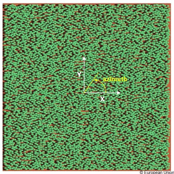
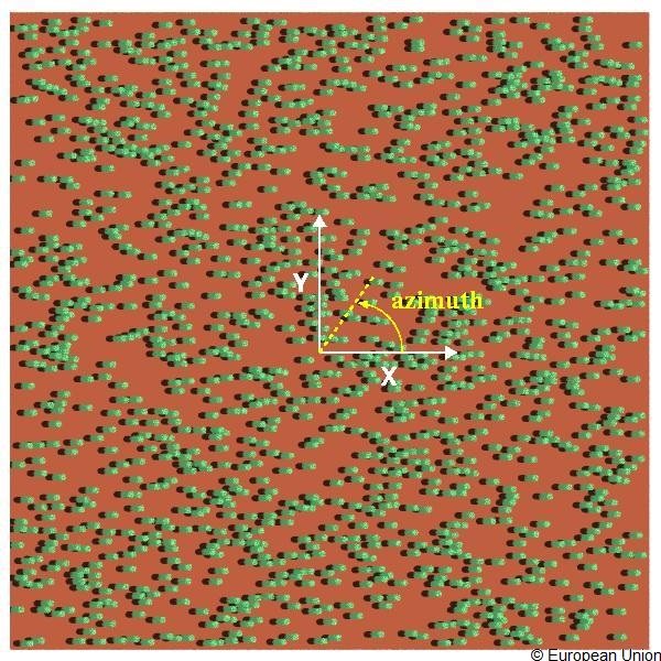
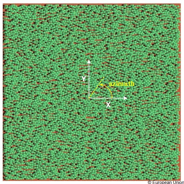
The figure shows azimuth angle counting scheme.
An ASCII file with the radius (R), centre coordinates (Xc,Yc,Zc), and direction cosines (Dx,Dy,Dz) of every single leaf in a cylindrical volume (centered at 0,0,0 but inclined via a 15 degree rotating around the Y axis such that the positive z axis moves towards the positive X axis) is available here. This files (are ~ 1.2 Mbytes and) contain 17999 lines of format R Xc Yc Zc Dx Dy Dz that may serve as input to your scene creation process (provided that you are able to create multiple instances of its content, each one of which is then translated to the actual locations of the cylinder centers in the scene. An ASCII file with the X, Y, Z cylinder center coordinates can be found here.
The table below provides detailed information regarding the illumination conditions and spectral properties of the foliage and background constituents of the sparse canopy scenarios.
The table is preceeded by the corresponding experiment identifier tag that is needed in the naming of the various measurement results files (see file naming and formatting conventions).
Two spectral bands (red and NIR) and four illumination conditions (direct only with SZA=20° and 50° for solar azimuths of 0° and 180°) are proposed.
Dense heterogeneous canopy with a constant slope of 15 degree
The table below provides the details required to build and run a RT model on the dense heterogeneous cylinder canopy with a constant inclination of 15 degree. Also indicated are the X and Y axes with the azimuth angle counting scheme.
experiment
HET24
( X × Y × Z) [m × m × m]
101.30 × 101.0 × 3.58
(Xmin, Ymin, Zmin) [m, m, m]
−50.65, −50.5, 0.0
(Xmax, Ymax, Zmax) [m, m, m]
+50.65, +50.5, 3.58
Scatterer shape
Disc of negligible thickness
Scatterer radius [m]
0.0075
Foliage scattering law
Bi-Lambertian
LAI of individual (upright) cylinder
4.05
radius of cylinder [m]
0.5
height of (upright) cylinder [m]
3.0
cylinder center height range [m]
2.0099 - 2.0101
Scatterer normal distribution
Uniform
Number of cylinders
5093
LAI of scene
1.58330
Background scattering law
Lambertian
The figure shows azimuth angle counting scheme.
An ASCII file with the radius (R), centre coordinates (Xc,Yc,Zc), and direction cosines (Dx,Dy,Dz) of every single leaf in a cylindrical volume (centered at 0,0,0 but inclined via a 15 degree rotating around the Y axis such that the positive z axis moves towards the positive X axis) is available here. This files (are ~ 1.2 Mbytes and) contain 17999 lines of format R Xc Yc Zc Dx Dy Dz that may serve as input to your scene creation process (provided that you are able to create multiple instances of its content, each one of which is then translated to the actual locations of the cylinder centers in the scene. An ASCII file with the X, Y, Z cylinder center coordinates can be found here.
The table is preceeded by the corresponding experiment identifier tag that is needed in the naming of the various measurement results files (see file naming and formatting conventions).
Two spectral bands (red and NIR) and four illumination conditions (direct only with SZA=20° and 50° for solar azimuths of 0° and 180°) are proposed.
Sparse heterogeneous canopy with a constant slope of 30 degree
The table below provides the details required to build and run a RT model on the sparse heterogeneous cylinder canopy with a constant inclination of 30 degree. Also indicated are the X and Y axes with the azimuth angle counting scheme.
experiment
HET33
( X × Y × Z) [m × m × m]
101.30 × 101.0 × 3.54
(Xmin, Ymin, Zmin) [m, m, m]
−50.65, −50.5, 0.0
(Xmax, Ymax, Zmax) [m, m, m]
+50.65, +50.5, 3.58
Scatterer shape
Disc of negligible thickness
Scatterer radius [m]
0.0075
Foliage scattering law
Bi-Lambertian
LAI of individual (upright) cylinder
4.05
radius of cylinder [m]
0.5
height of (upright) cylinder [m]
3.0
cylinder center height range [m]
2.0099 - 2.0101
Scatterer normal distribution
Uniform
Number of cylinders
1274
LAI of scene
0.396058
Background scattering law
Lambertian
The figure shows azimuth angle counting scheme.
An ASCII file with the radius (R), centre coordinates (Xc,Yc,Zc), and direction cosines (Dx,Dy,Dz) of every single leaf in a cylindrical volume (centered at 0,0,0 but inclined via a 30 degree rotating around the Y axis such that the positive z axis moves towards the positive X axis) is available here. This files (are ~ 1.2 Mbytes and) contain 17999 lines of format R Xc Yc Zc Dx Dy Dz that may serve as input to your scene creation process (provided that you are able to create multiple instances of its content, each one of which is then translated to the actual locations of the cylinder centers in the scene. An ASCII file with the X, Y, Z cylinder center coordinates can be found here.
The table below provides detailed information regarding the illumination conditions and spectral properties of the foliage and background constituents of the sparse canopy scenarios.
The table is preceeded by the corresponding experiment identifier tag that is needed in the naming of the various measurement results files (see file naming and formatting conventions).
Two spectral bands (red and NIR) and four illumination conditions (direct only with SZA=20° and 50° for solar azimuths of 0° and 180°) are proposed.
Dense heterogeneous canopy with a constant slope of 30 degree
The table below provides the details required to build and run a RT model on the dense heterogeneous cylinder canopy with a constant inclination of 30 degree. Also indicated are the X and Y axes with the azimuth angle counting scheme.
experiment
HET34
( X × Y × Z) [m × m × m]
101.30 × 101.0 × 3.54
(Xmin, Ymin, Zmin) [m, m, m]
−50.65, −50.5, 0.0
(Xmax, Ymax, Zmax) [m, m, m]
+50.65, +50.5, 3.58
Scatterer shape
Disc of negligible thickness
Scatterer radius [m]
0.0075
Foliage scattering law
Bi-Lambertian
LAI of individual (upright) cylinder
4.05
radius of cylinder [m]
0.5
height of (upright) cylinder [m]
3.0
cylinder center height range [m]
2.0099 - 2.0101
Scatterer normal distribution
Uniform
Number of cylinders
5093
LAI of scene
1.58330
Background scattering law
Lambertian
The figure shows azimuth angle counting scheme.
An ASCII file with the radius (R), centre coordinates (Xc,Yc,Zc), and direction cosines (Dx,Dy,Dz) of every single leaf in a cylindrical volume (centered at 0,0,0 but inclined via a 30 degree rotating around the Y axis such that the positive z axis moves towards the positive X axis) is available here. This files (are ~ 1.2 Mbytes and) contain 17999 lines of format R Xc Yc Zc Dx Dy Dz that may serve as input to your scene creation process (provided that you are able to create multiple instances of its content, each one of which is then translated to the actual locations of the cylinder centers in the scene. An ASCII file with the X, Y, Z cylinder center coordinates can be found here.
The table below provides detailed information regarding the illumination conditions and spectral properties of the foliage and background constituents of the sparse canopy scenarios.
The table is preceeded by the corresponding experiment identifier tag that is needed in the naming of the various measurement results files (see file naming and formatting conventions).
Two spectral bands (red and NIR) and four illumination conditions (direct only with SZA=20° and 50° for solar azimuths of 0° and 180°) are proposed.